Authors:
V. Lapin
A. Astahov
Intensification of oil refining processes is a promising task of modern production. From an economic and environmental point of view, waste reduction and maximum use of natural resources is important. These problems can be successfully solved by means of catalysis. The article provides examples of catalytic reactions that are often used in production. Some reactions occurring in laboratory catalytic plants developed by "Research and Production Company "Meta-chrom Co. Ltd." are given in details. The designs of a number of laboratory reactor plants are described: for testing PEC-1 catalysts, evaluating the activity of heterogeneous catalysts, and determining the properties of a fine KDI-M catalyst. he prospects for the use of donor-solvent thermal cracking to reduce the viscosity of super-viscous oil and heavy petroleum products are being discussed.
Catalysis is a process of selective acceleration of chemical reactions under the action of catalysts - substances that repeatedly participate in chemical transformation, but are practically not consumed. Catalysis is widely distributed in nature and is used in industrial chemical technologies, in particular, refining, for example, in the production of motor fuels, alcohols, acids, aldehydes, phenol, synthetic resins and plastics, artificial rubbers, dyes, etc.
The use of catalysts has a wide range of advantages. First, they provide a high direction of the chemical transformations that occur, the proportion of by-products decreases (up to their full exception), while simplifying the cleaning process. Secondly, an increase in the yield of target substances under conditions of catalysis can significantly reduce the consumption of energy and material resources necessary for their production. Often the processes take place in more soft and less energy-intensive conditions. Thirdly, in reactions, catalysts are used in relatively small quantities, are practically not consumed, and therefore ideally do not require renewal and regeneration. In general, all this makes the use of catalysis in chemical technologies attractive and cost effective.
Catalytic processes are widely used
in oil refining and petrochemistry. Let us give examples of catalytic reactions.
Catalytic reforming is used for producing high octane components of car gasolines, flavored concentrate for the production of individual aromatic hydrocarbons, as well as technical hydrogen.
As raw materials for reforming it is used straight-run gasoline fractions, as well as hydrocracking and thermal cracking gasolines. The products of reforming are hydrocarbon gas, catalysate, hydrocarbons С3 - С4 and С3 - С5, hydrogen-containing gas.
Reforming catalysts belong to the class of metal-oxide catalysts prepared by applying a small amount of metal on a refractory carrier. Previously monometallic catalysts were used, modern catalysts are polymetallic. To prevent deactivation of the catalyst, the content of sulfur and nitrogen in the raw materials is limited.
Catalytic reforming plants are divided according to the method of carrying out oxidative regeneration of the catalyst into two types. There are plants with a stationary bed, where regeneration is carried out once or twice a year and is associated with a stop of production, and plants with a moving catalyst bed, where regeneration takes place in a special apparatus.
Isomerization of paraffinic hydrocarbons is used to increase the octane number of С5 - С6 oil fractions by converting paraffins of normal structure to their isomers with a higher octane number.
Light-weight straight-run fractions are used as raw materials, and the product is isocomponent, which is mixed with products of reforming and catalytic cracking to produce high-octane gasolines.
At Russian refineries domestic catalysts of type SI-1 and catalysts developed by the company «UOP» are used.
Hydrotreating of distillates is carried out to improve the quality and stability of light distillates, catalytic cracking raw materials, using destructive hydrogenation of organic sulfur
compounds and hydrogenation of unsaturated hydrocarbons. Gasoline, kerosene, diesel fractions and vacuum gas oil containing sulfur, nitrogen and unsaturated hydrocarbons are used as raw materials. The products are refined fractions, distilled gasoline, as a component of commercial gasoline, and hydrogen sulfide, as a raw material for the production of sulfuric acid or sulfur.
In industry, alumino-cobalt-molybdenum and alumo-nickel-molybdenum catalysts are used for distillate hydrotreating plants.
Catalytic cracking is needed to obtain additional amount of light oil, namely, high-octane gasoline and diesel fuel, by decomposition of heavy petroleum fractions in the presence of a catalyst. The most commonly used raw material is a vacuum distillate obtained by the primary distillation of oil, and also coking, thermal cracking and hydrocracking gas oils. The products are hydrocarbon gas, gasoline fraction, light gas oil.
Synthetic aluminosilicate amorphous and zeolite-containing catalysts are used in Russian catalytic cracking plants.
Alkylation of isobutane with olefins is used to produce gasoline fractions with high stability and detonation resistance. The interaction of isobutane with olefins occurs in the presence of a catalyst. Raw materials - isobutane and butane butylene fraction, as well as propane-propylene and pentane-amylene fractions. Products - light alkylate and liquefied gases. Sulfuric acid is used as a catalyst, abroad hydrofluoric acid is used along with sulfuric acid.
Polymerization (oligomerization) of olefins is used to produce low molecular weight polymers (oligomers) of propylene and butylene, which are used as motor fuel or as a raw material for petrochemical synthesis. Raw materials for polymerization plants are propane propylene and butane-butylene fractions, and products are polymerbenzene and isooctylene. Polymerization (oligomerization) is carried out in the presence of phosphoric acid on the carrier.
Hydrocracking is used to obtain an additional amount of light oil by catalytic decomposition of heavy raw materials in the presence of hydrogen. A wide range of petroleum fractions, from gasoline to heavy residues (fuel oil and tar), is used as raw materials for hydrocracking plants. The most common type of raw material is vacuum distillate of straight distillation of petroleum, which is processed in pure form or mixed with coking, thermal and catalytic cracking gas oils. Products are: liquefied gas, gasoline, kerosene and diesel fractions.
Thermal cracking and visbreaking are used to obtain: in the thermal cracking mode – an additional amount of light oil products by thermal decomposition of residues from the oil refining; in the visbreaking mode – improving the quality of the boiler house fuel. Raw materials are residues of primary oil refining - fuel oil and tar. Products – gas containing unsaturated and saturated hydrocarbons and hydrogen sulfide, gasoline, kerosene and gas oil fraction, cracking residue.
Coking is used to produce petroleum coke and an additional amount of light oil from heavy residues. The raw material used is tar, the residue of thermal cracking, heavy gas oil. Products are, for example, petroleum coke.
Continuous improvement of all the listed technologies requires initial development of the conditions for their implementation on a small scale, far from large-scale production. For this purpose, laboratory (pilot) catalytic plants are used, where you can test a new catalyst, study and test its properties, optimize reaction modes, test the latest developments in petrochemistry. Such equipment is indispensable for conducting research works, developing refining processes based on advanced technologies and for training specialists. "Research and Production Company "Meta-chrom Co. Ltd." has been engaged for more than five years to the creation and implementation of such equipment. During this time, extensive experience has been gained in cooperation with large oil refining enterprises (Gazprom Neftekhim Salavat, Nizhnekamskneftekhim, Ishimbay Specialized Chemical Plant of Catalysts, Nizhny Novgorod Catalysts, etc.) and with research (GOSNIIHP, IOFH A.E.Arbuzov KazSC RAS, KHTU KazSC RAS) and educational institutions (Lomonosov Moscow State University).
The reactor equipment for each process unit is designed according to a special (individual) project. To characterize the reactors, the following indicators are used: type of chemical reaction, performance, geometrical dimensions and shape, design technological parameters (pressure, temperature, space velocity, etc.), material performance, etc. In the refining industry, as a rule, continuous reactors are used. Plants of periodic action are used only in low-tonnage and auxiliary processes.
The equipment developed and manufactured in "Research and Production Company "Meta-chrom Co. Ltd." compares favorably with imported counterparts. First, its price is 2-3 times lower. Secondly, the developed installation scheme most fully meets the conditions of the reaction due to the deep penetration of developers into the essence of the task. Thirdly, maintenance and repair is cheaper, and it is also possible to modernize the plant for new purposes. We work in close cooperation with the customer from the moment of setting the task and drawing up the technical specification to the introduction of the plant into production.
Let us give examples of some reactions occurring in laboratory catalytic plants developed by "Research and Production Company "Meta-chrom Co. Ltd.".
1.Manufacture of benzene
1.1Testing of catalysts for hydrostabilization and hydrotreatment of the benzene-toluene fraction (BT fraction). The purpose of the first stage of hydrogenation processing is to hydrostabilize the BT fraction.
In the first stage, the BT fraction is subjected to hydrogenation in the presence of a palladium catalyst in a reactor, where the most unstable reactive unsaturated hydrocarbons are selectively hydrogenated. The diene and 90% vinyl groups of styrene, olefinic and cycloolefinic hydrocarbons are saturated with forming the corresponding hydrocarbons: olefins, ethylbenzene, paraffins, naphthenes. The process of hydrogenation occurs in the liquid phase. The polymerization rate of reactive unsaturated hydrocarbons increases with increasing the process temperature.
The double bond hydrogenation reaction is equilibrium, but at low temperatures it is shifted towards the formation of saturated hydrocarbons. The reaction heat during the hydrogenation of olefinic hydrocarbons is 24–31 kcal/mol and depends on the position of the double bond. Hydrogenation of double bonds proceeds through first order reactions. Polymerization is a higher order reaction and its rate is highly dependent on the concentration of the reactants.
The use of hydrogenate in the process of hydrogenation to dilute the primary liquid raw materials reduces the rate of polymerization reactions in the reaction mixture, which allows you to adjust the temperature in the first-stage reactor.
Examples of hydrogenation reactions occurring in the reactor:
CH2= CH-CH2=C-CH3+H2 = CH3-CH2-CH=C-CH3+29,5 kcal/mol (1)
||
CH3СH3
4-метилпентадиен-1,32-methylpentene-2
С6Н5 - CH= CH2 +H2 = С6Н5-CH2-CH3 + 30 kcal/mol (2)
стиролethylbenzene
CH3-СH2-CH = С-CH3+ H2 = CH3-CH2-CH2-CH-CH3 + 27,2 kcal/mol (3)
||
CH3СН3
2-methylpentene-22-methylpentene
CH2= CH-(CH2)4-CH3+ H2 = CH3-(CH2)5-СН3+ 31,0 kcal/mol (4)
heptane-1heptane
С6Н10 + H2 = С6Н12+ 28 kcal/mol (5)
Hydrogenation conditions:
- the ratio of hydrogen to the raw material not less than 200 Nm3 /m3;
- volumetric rate of the raw material 3 h-1;
- pressure 35-49 kgf/cm2;
- temperature 70 - 175 0С;
- frequency of recycling to raw materials (0,6 - 1,5):1 .
1.2. The purpose of the second stage is the desulfurization of the BT fraction (hydrogenate of the first stage) and the complete saturation of unsaturated hydrocarbons in the reactor using aluminum cobalt-molybdenum and aluminum nickel-molybdenum catalysts.
Examples of desulfurization reactions (hydrogenolysis of organic sulfur compounds) with the formation of hydrogen sulfide and saturated hydrocarbons, as well as the full saturation of unsaturated hydrocarbons of the hydrogenate of the first stage:
C4H4S + 4H2 = C4H10 + H2S - 67 kcal/mol (6)
thiophenebutane
(С3H7)2S + 2H2 = 2C3H8 + H2S - 28 kcal/mol (7)
dipropylsulfide propane
С7Н14S + 2H2 = C7H16 + H2S - 16,8 kcal/mol (8)
heptylmercaptan heptane
The heat of hydrodesulfurization rections can be neglected due to the low content of sulfur compounds in the raw material.
Hydrogenation conditions:
- the ratio of hydrogen to raw materials (600-1000) v/v;
- pressure 35-47 kgf/cm2
- temperature 300-3600 С;
- raw material flow rate 2 h-1.
2. Production of ethylbenzene
Alkylation of benzene with ethylene is an exothermic reaction that occurs in the presence of a zeolite catalyst. The alkylation reaction occurs by an electrophilic mechanism. Ethylene is protonated on the acid with the formation of highly active intermediate compound. The main alkylation reaction with the formation of ethylbenzene occurs as follows:
С6Н6 + С2Н4 → С6Н5С2Н5 (9)
benzene ethylene ethylbenzene
ΔН = -27,19 kcal/mol = - 113,84 kJ/mol
In addition to the main reaction in the alkylation reactor, side reactions occur, both with the participation of the main raw material and with the participation of impurities contained in the raw material.
So, because of the acid catalyst, ethylene can react with the resulting ethylbenzene to the formation of diethylbenzene isomers:
С6Н5С2Н5 + С2Н4 → С6Н4(С2Н5)2 (10)
ethylbenzene ethylene triethylbenzene
ΔН = -25,82 kcal/mol = - 108,103 kJ/mol
In addition to the isomers of diethylbenzene, other polyethylbenzenes can also be formed (mainly with three or four ethyl groups), but in much smaller quantities. Other side reactions lead to the formation of diphenylethanes and in a small amount of light paraffins and other alkyl aromatic compounds:
С6Н5С2Н5 + 2С2Н4 → С6Н3(С2Н5)3 (11)
ethylbenzene ethylene triethylbenzene
С6Н6 + С3Н6 → С6Н5С3Н7 (12)
benzene propylene isopropylbenzene
2С6H6 + С2Н2 → С6Н5 – СН- С6Н5 (13)
|
CH3
benzene acetylene 1,1-diphenylethane
Toluene (admixture of fresh benzene) is alkylated with the formation of ethyltoluene:
С6Н5СН3 + С2Н4 → СН3 – С6Н4 – С2Н5 (14)
toluene&nbethyleneethyltoluene
As a result of the destruction of alkyl groups at alkylation xylenes are produced:
С6Н5С2Н5 +Н2 → С6Н4(СН3)2 (15)
ethylbenzene ortho (pair)-xylene
The reaction rate of the formation of xylenes increases with increasing temperature. The necessary hydrogen is released due to the dehydrocondensation reaction of aromatic compounds, as a result of which resinous substances depleted in hydrogen are obtained (coke formation reactions.
The alkylation process can be either gas or liquid phase, depending on the catalyst used.
Conditions of gas-phase process:
Raw materialmixture of benzene with ethylene
Molar ratio B/E7/1
Temperature, °С360- 420
Fresh feed rate, h-115
Conditions of liquid-phase process:
Raw materialmixture of benzene with ethylene
Molar ratio B/E5,5/1
Temperature, °С200-240
Fresh feed rate, h-15
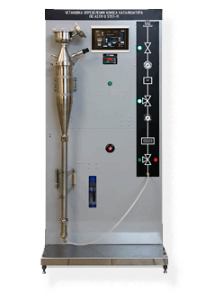
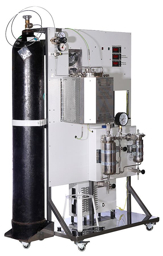
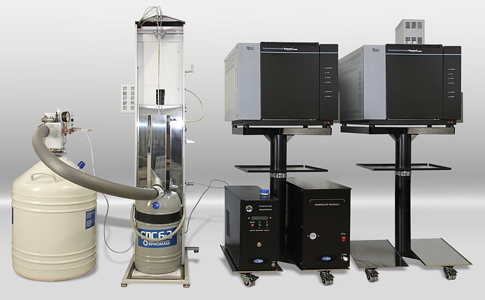
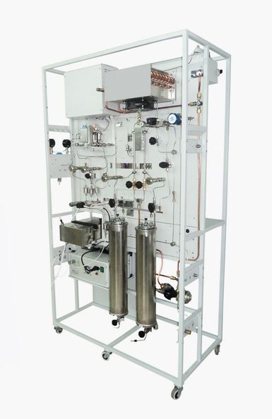
The laboratory reactor plant for testing catalysts PEC-1 (Fig. 1, 2) is an installation for the alkylation of benzene with ethylene (reaction (9), see above). Determination of the catalyst quality is carried out in a wide range of reactions under industrial conditions at temperatures up to 600 °C and pressures up to 10 MPa.
The plant includes:
• automatic generation system of dosed gas flows (up to four channels) with microprocessor control. Modes of operation are set and displayed on a PC monitor. At the entrance of each gas line there is a manual ball valve and pressure gauge. Parallel to one of the electronic flow regulators it is fixed a needle valve for purging the plant and filling it with inert gas.
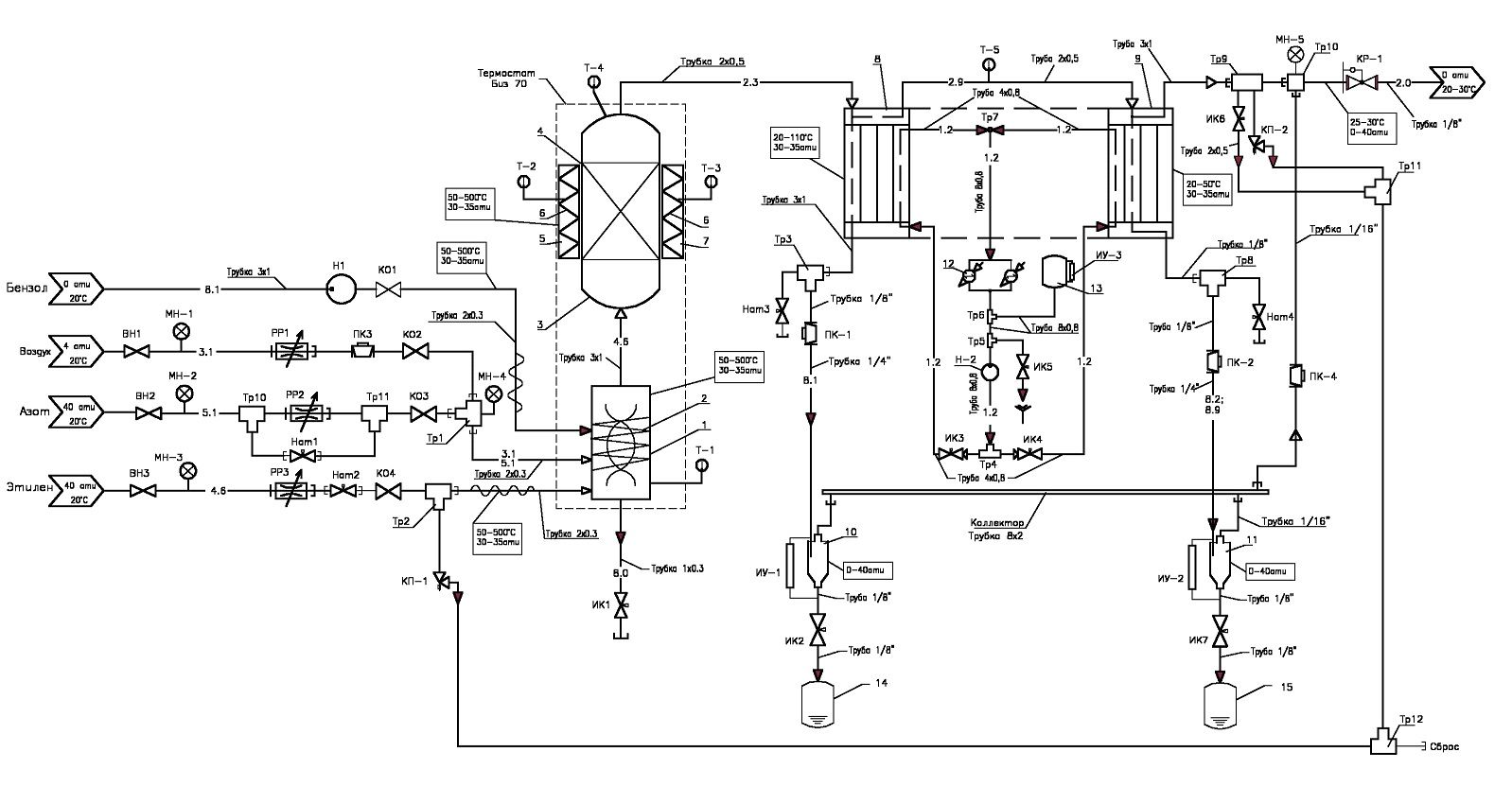
Fig. 1: Diagram of a pneumatic installation for the alkylation of benzene with ethylene.
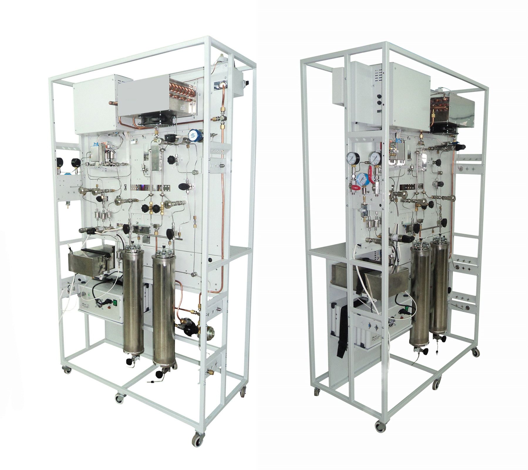 Fig. 2: External view of the reactor installation.
• system of automatic formation of the dosed fluid flow by a high-pressure pump.
• thermostatted mixer, in which the evaporation of liquids entering into it, heating of gases and the formation of a vapor-gas mixture occurs. The microprocessor controls operation of the mixer, and personal computer forms and displays the modes of operation.
• thermostatted reactor, in which the temperature is maintained by a sliding two-section heater in the range from 50 to 600 °C. Each section has its own heater and temperature sensor. The microprocessor controls operation of the thermostat, and personal computer forms and displays the modes of operation. The volume and dimensions of the reactor are specified when ordering.
• refrigerator in the form of a spiral tube, enclosed in a shirt with cooling fluid. Volume of the refrigerator and its performance is specified and calculated when ordering. The refrigerator operates at pressures up to 10 MPa. Water, antifreeze, etc. can be used as a cooling fluid. The cooling system is closed and contains a pump and cooling radiator with fan. If negative temperatures are needed, a refrigeration unit with a heat exchanger should be installed. The refrigerator can be single-stage or two-stage, while the second stage can be used to separate the light boiling fraction, and to increase productivity due to sequential inclusion. The first and the second stages of the refrigerator are interconnected by a pipeline with a temperature sensor built into it. This allows you to adjust the refrigerator to the desired temperature by adjusting the flow rate of the refrigerant flowing through the cooling jackets with needle valves. At the outlet of the refrigerator, needle and plug valves are installed. The needle valve is used for sampling at the outlet of the refrigerator for analysis at an operating pressure of up to 10 MPa. A plug valve connects the outlet of the refrigerator to a high-pressure separator equipped with a tap to drain the liquid and a level sensor, information about which is transmitted to the computer.
• an automatic pressure maintenance system in the range of 0–5 MPa, performed on a mechanical pressure regulator. Constant pressure is maintained automatically by discharging a portion of the gas fraction (usually inert gas and vapor of the mixture components) into the gas meter or into the atmosphere.
• System of automatic control and protection against excess pressure in the installation. It consists of electronic pressure transducers installed before and after the reactor, as well as mechanical safety valves to protect against excess pressure, usually adjusted to 0.5 MPa higher than the operating pressure in the system. When the safety valves are activated, the vapor-gas mixture is discharged into the drainage system, the outlet of which is connected to the atmosphere or the container for disposal. Information from the electronic pressure transducers installed before and after the reactor is transmitted to the computer and displayed on the monitor screen. When the specified pressure threshold is exceeded, the supply of liquids and gases to the unit is automatically stopped, the flows of which are formed by pumps and electronic gas flow regulators.
• If necessary, the system can be equipped with a low-pressure gas-liquid separator with pressure control and automatic temperature maintenance in the thermostatic jacket. The gas component is discharged through the gas line under atmospheric pressure, the condensed liquid flows into the receiver flask.
• The unit is equipped with a with a gas chromatograph «Crystallux 4000M» for analyzing the composition of the vapor-gas mixture, discharged gases and liquids.
• The supply voltage of the system is 220 V, 50 Hz. Power consumption is not more than 1.0 kW.
• With the help of a computer program, reports are created and stored with the data that the operator chooses: the set of measured temperatures, pressures and consumptions during the experiment. Another software function is a detailed control of the current situation at the operator’s chosen deviation limits for the reaction parameters from the specified values. With the help of the program, the plant disconnects from the mains at unacceptable deviations of the supported parameters.
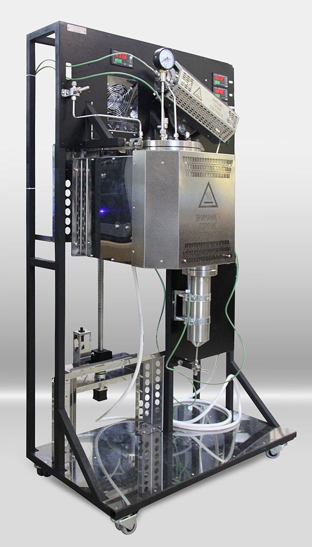
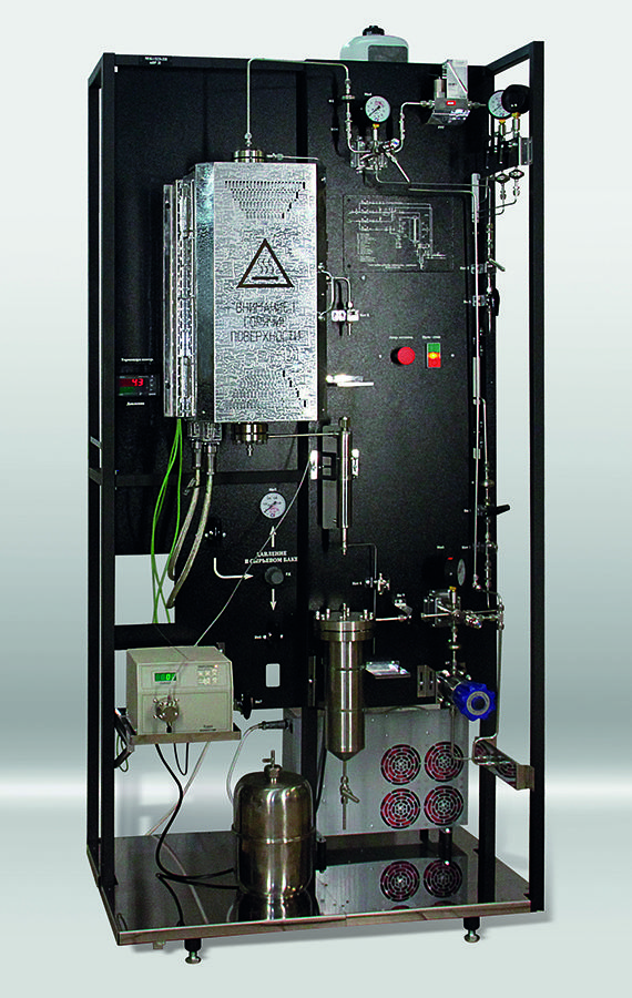
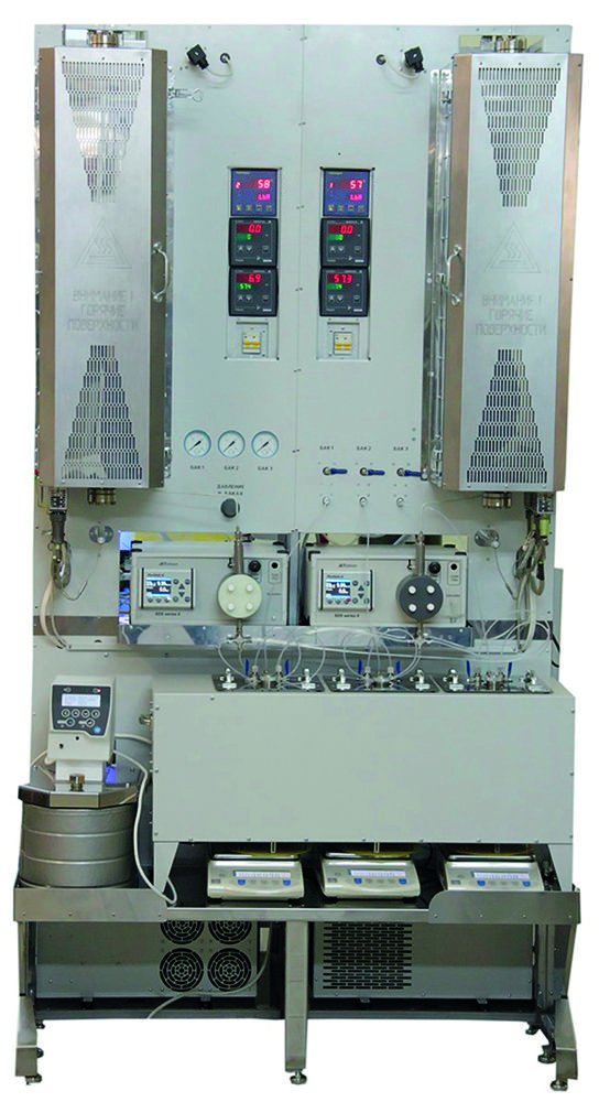
The laboratory plant for assessing the activity of heterogeneous catalysts (Fig. 3, 4) in a fixed-bed reactor is intended for hydrotreatment of the benzene-toluene fraction (BT-fraction, reactions (1) - (5), see above). Hydrogenation of double bonds proceeds through first order reactions. The reaction heat during the hydrogenation of olefinic hydrocarbons is 24–31 kcal/mol and depends on the position of the double bond. Saturation of the diene and vinyl groups of styrene, olefinic and cycloolefinic hydrocarbons occurs with the formation of the corresponding hydrocarbons: olefins, ethylbenzene, paraffins, naphthenes.
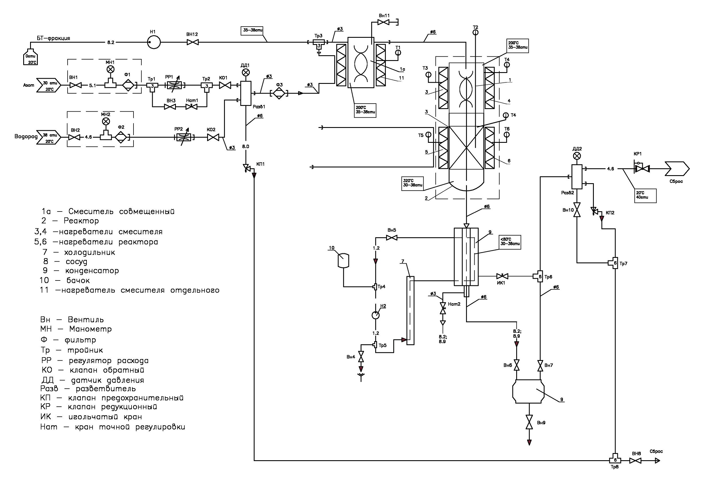
Fig. 3: The pneumatic circuit test system for testing catalysts of the process.
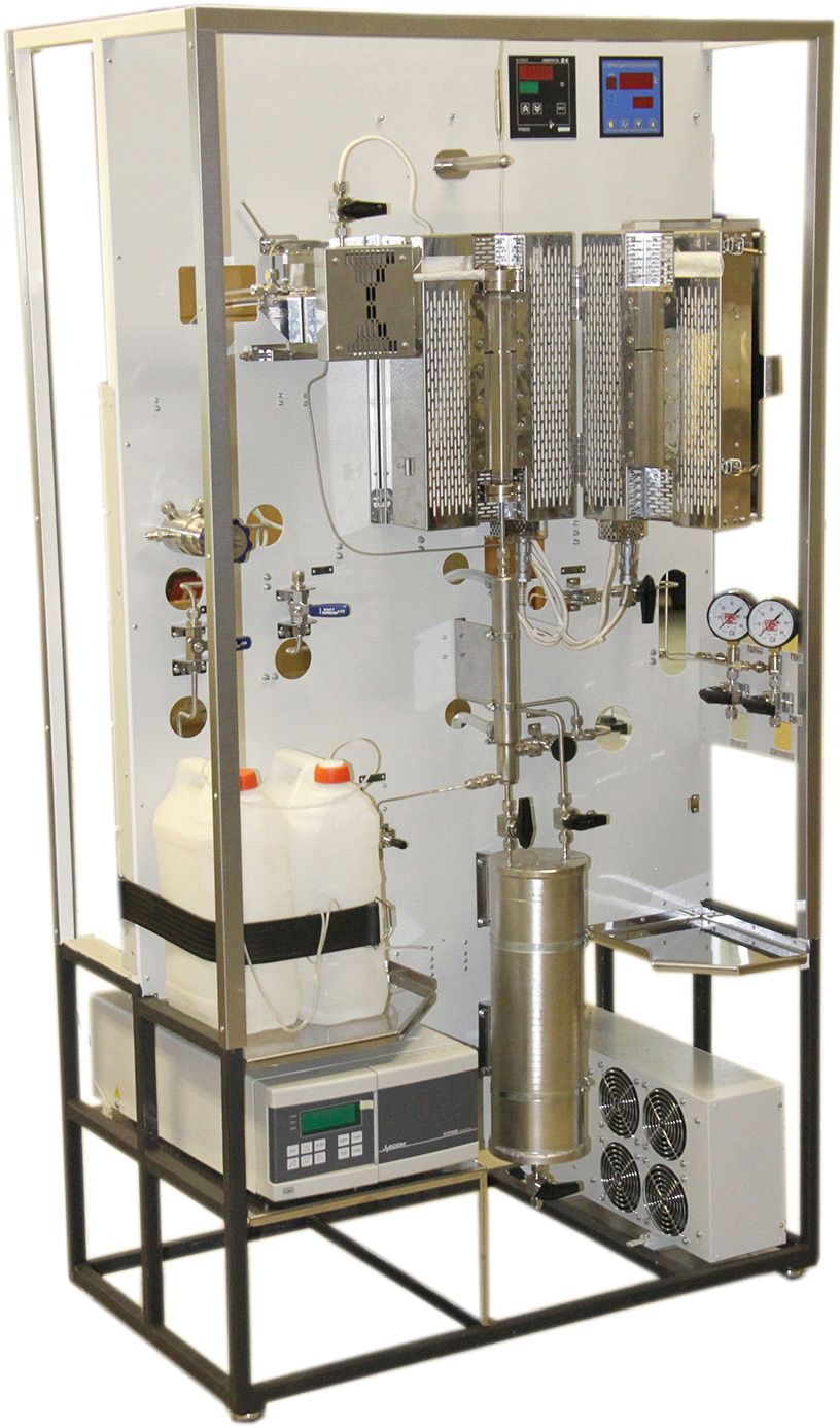 Fig. 4: Appearance of the benzene-toluene fraction Hydrotreating unit with direct-flow mixer.
The plant includes:
• BT-fraction flow formation system made on the base of a plunger pump. The initial BT-fraction is stored in two cans fixed on the plant and connected by a flexible fluoroplastic capillary with the inlet of the plunger pump. Control of the pump, control of parameters and malfunctions is carried out with the help of a program installed on the supplied PC. From the pump, the BT-fraction is fed to the mixer, which can be made as a separate thermostatically controlled tank. Functions of the mixer can be carried out by the first zone of the reactor, having a spiral insert and an independent thermostat.
• hydrogen flow forming system. It consists of connected in series input shut-off valve, tee with fixed on it pressure gauge for the control of pressure in the hydrogen line, filter for cleaning off mechanical particles, electronic flow regulator controlled with the help of a personal computer and a check valve that prevents the BT-fraction and catalyst from entering the proportional valve of the flow regulator.
• nitrogen flow formation system, which includes connected in series an inlet shut-off valve, a tee with a pressure gauge fixed on it, a filter for cleaning off mechanical particles and a gas flow regulator. In parallel with the gas flow regulator, a valve and a leak valve are switched on, designed to accelerate nitrogen inlet and to form the working pressure at the first stage of the plant operation. At the outlet of the system, a check valve is installed, which prevents the BT-fraction and catalyst from entering into the system.
• a mixer, made in the form of a thermostatically insulated, heat-insulated cylindrical tank into which nitrogen, hydrogen and the BT-fraction are fed. The nitrogen used to purge and displace air from the mixer is removed through an open valve installed on the cover of the mixer. As a mixer, a reactor zone equipped with a separate thermostat can be used, in the internal volume of which quartz sand or a spiral insert can be located. Heat transfer between the heated inner surface of the reactor and components to be mixed is carried out due to the movement of hydrogen and the BT-fraction in a spiral.
• Рreactor, which is a section of pipe with flanges at both ends with covers equipped with supply lines. Sealing gaskets are made of aluminum foil, graflex or brass foil coated with a thick layer of silver. On the reactor body it is made an incision separating the working zone of the reactor from the preheating zone (mixer). A thermocouple pocket is coaxially located in the reactor chamber. A two-zone folding stove heats and maintains the required temperature in the reactor. It consists of a thermostatted stainless steel sectional housing, on which four heaters and four thermocouples are fixed.
• a cylindrical condenser for cooling the mixture leaving the reactor is surrounded by a jacket with coolant. The refrigeration plant consists of a pump, radiator, fans, drain valves and refrigerant flow control, as well as auxiliary tank. Inside the condenser there is a spiral insert through which the mixture flows, in contact with the cooled inner walls. At the bottom of the condenser there is a cavity that has two functions. The first – as a separator for preliminary separation of liquid and gas streams, the second – as a cumulative capacity of 5 ml, from which samples are taken through the leak valve for analysis and removal of substandard product at the initial test stage.
• the high-pressure storage separator – a 3-liter tank, at the bottom of which a valve is installed to drain the fluid, and on the cover there are two valves, one connected to the condenser and the other to the gas release and automatic pressure maintenance system. The pressure transducer monitors the pressure and transmits a digital signal that is displayed on the computer screen.
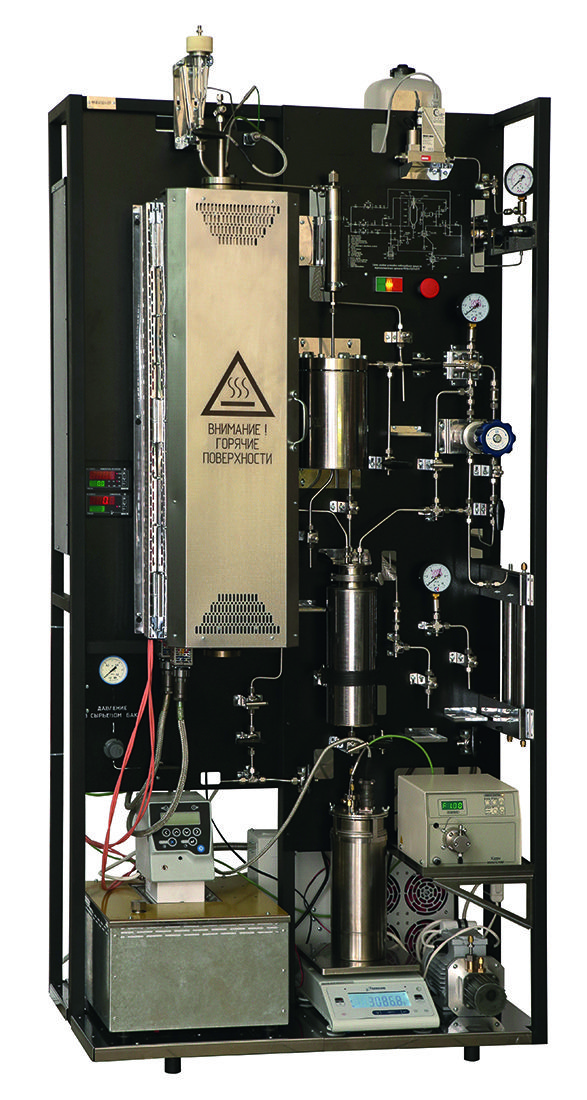
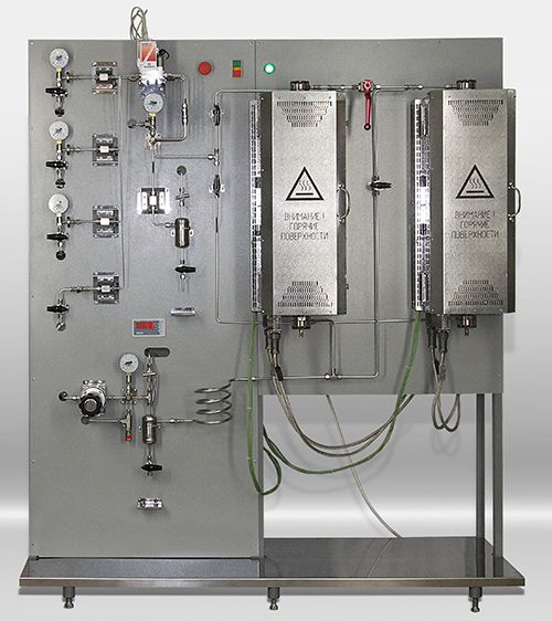
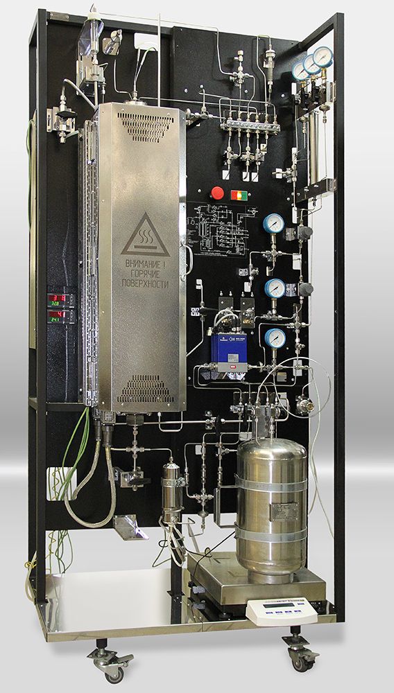
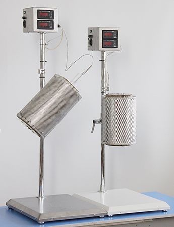
Laboratory installation for determination of properties of fine catalyst KDI-M (Fig. 5, 6), used in the preparation of isobutene from isobutane.
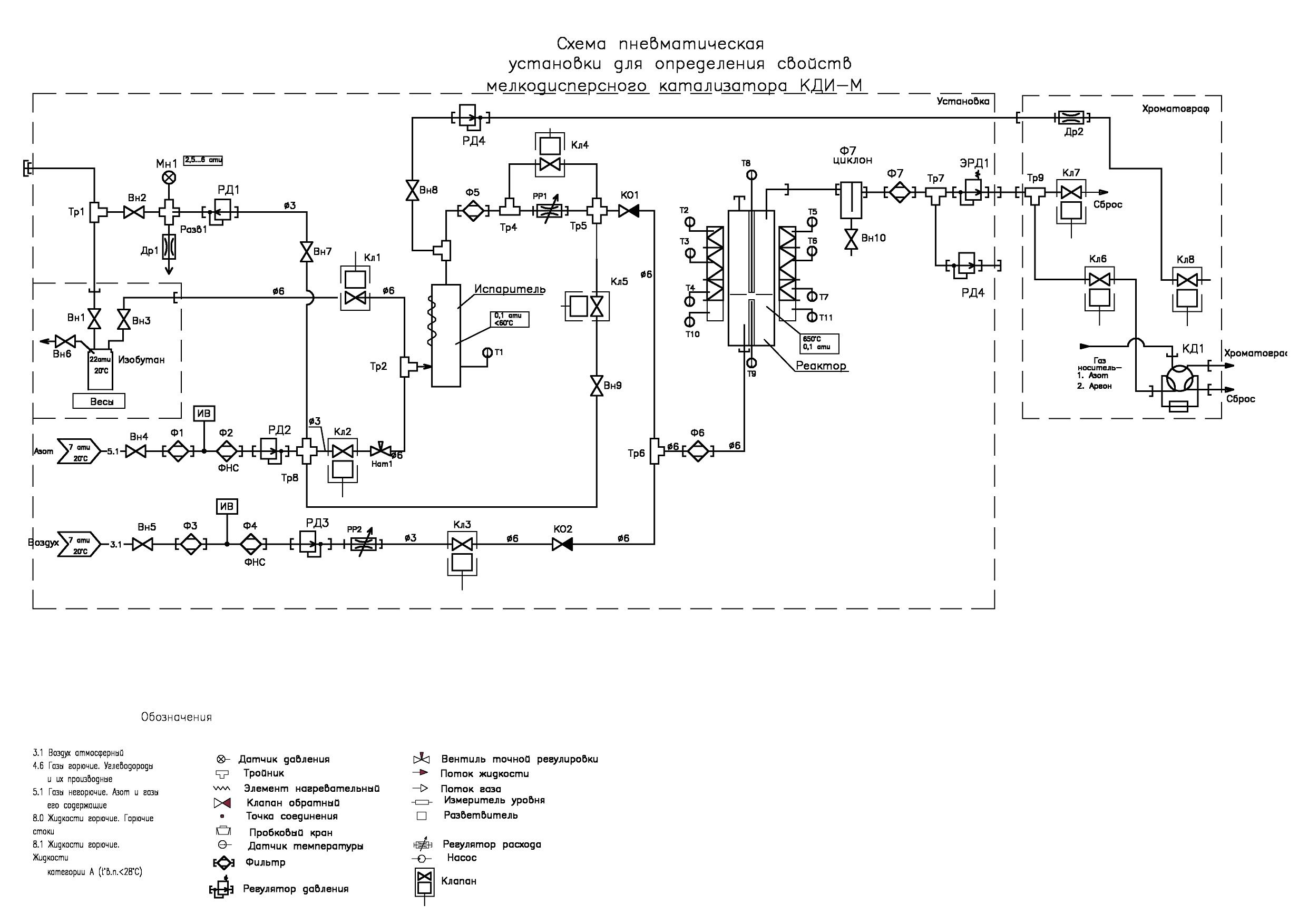
Fig. 5: Appearance of the plant for defining properties of finely dispersed catalyst KDI-M.
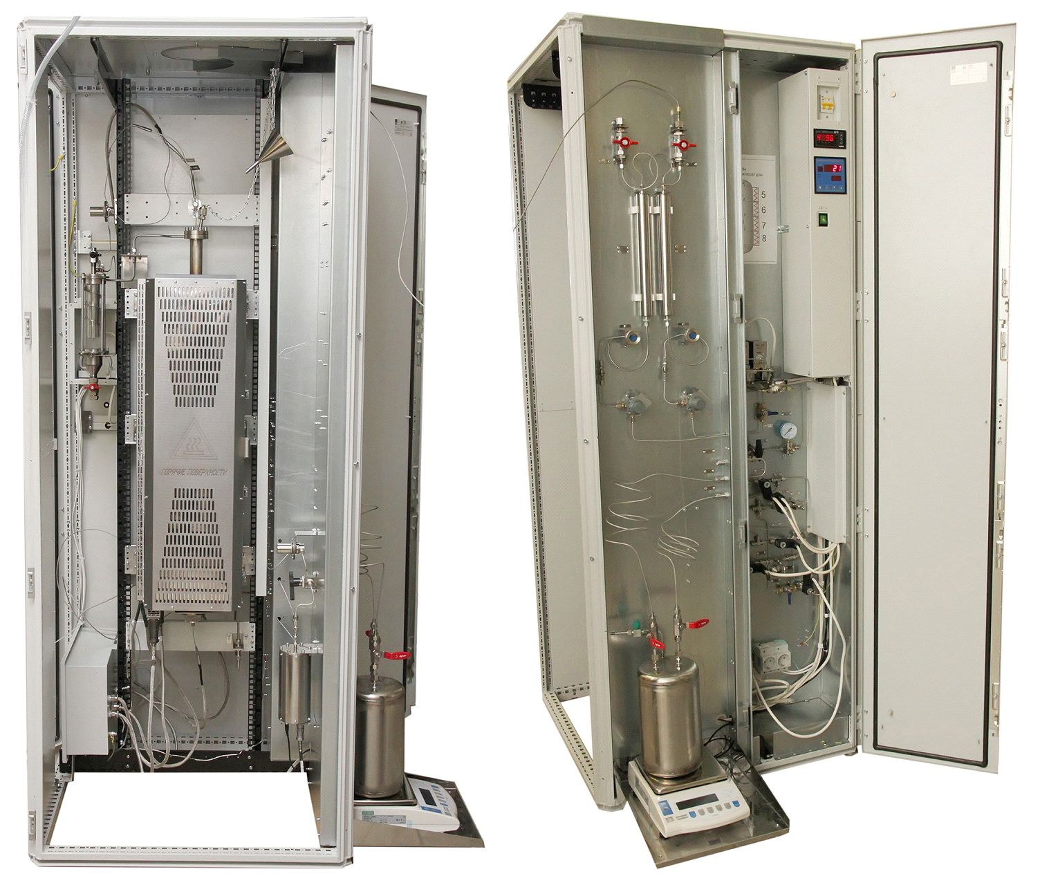 Fig. 6: The appearance of the installation.
The plant includes:
• isobutane storage and weighing system. It consists of a 5-liter tank mounted on a scale with a range of 15 kg and an error of ± 0.1 g. The system includes a pressure regulator connected to the nitrogen line. It is necessary for the formation of a nitrogen blanket in a cylinder with isobutane and to create in it the pressure necessary for squeezing isobutane from the cylinder into evaporator. A pressure gauge controls the outlet pressure of the regulator.
• shaper of the stream of nitrogen required for purging the system and removing air from it before starting work, as well as removing residues of isobutane after its completion.
• electronic regulator of the gas consumption, which creates a stream of air necessary for purification (oxidation) of residues of the investigated product. At the regulator outlet there is a check valve, which excludes entering isobutane vapor in the air line.
• a device for forming a stream of isobutane in the form of a tube lowered to the bottom of the tank through which the isobutane is squeezed out with the help of nitrogen blanket. The nitrogen blanket is created by a pressure regulator connected by its inlet with a line of nitrogen.
• reactor furnace with four independent heating zones, in each you can set and maintain its own temperature value. Each zone is heated by two heaters: one is located inside the fixed half of the furnace mounted on the rack, and the second is in its opening part. In close vicinity to the reactor in the center of each heated zone there is a thermocouple sensor. The temperature is maintained by a 12-channel thermoregulator located in the lower left corner of the plant box in the automation unit.
• The reactor is made of titanium pipe with an outer diameter of 32 mm. In the upper part of the reactor there is a flange with a lid on which the gateway for filling the catalyst and a pocket for thermocouples controlling the temperature inside the reactor are located. At the bottom of the reactor, at a distance of 150 mm from its lower end, a gas-permeable membrane is fixed, made of quartz glass fabric without a sizing agent. The membrane divides volume of the reactor into two parts.
• a heat exchanger in the form of a helical insert, along which isobutane vapor is moving, in contact with the heated walls of the reactor vessel and mixing when moving in a spiral. The lower end of the reactor ends with a threaded bushing with a cap nut with a gasket. Having unscrewed the nut, you can pull out the spiral insert with the membrane fixed on it and pour the catalyst out of the reactor. Then, it is advisable to use a wad attached to a ramrod to remove catalyst residue retained by electrostatic charge from the walls of the reactor. In the center of the spiral insert there is a pocket for a thermocouple. It controls the temperature of the gas passing through the membrane and, if necessary, corrects the temperature of the lower zone of the reactor.
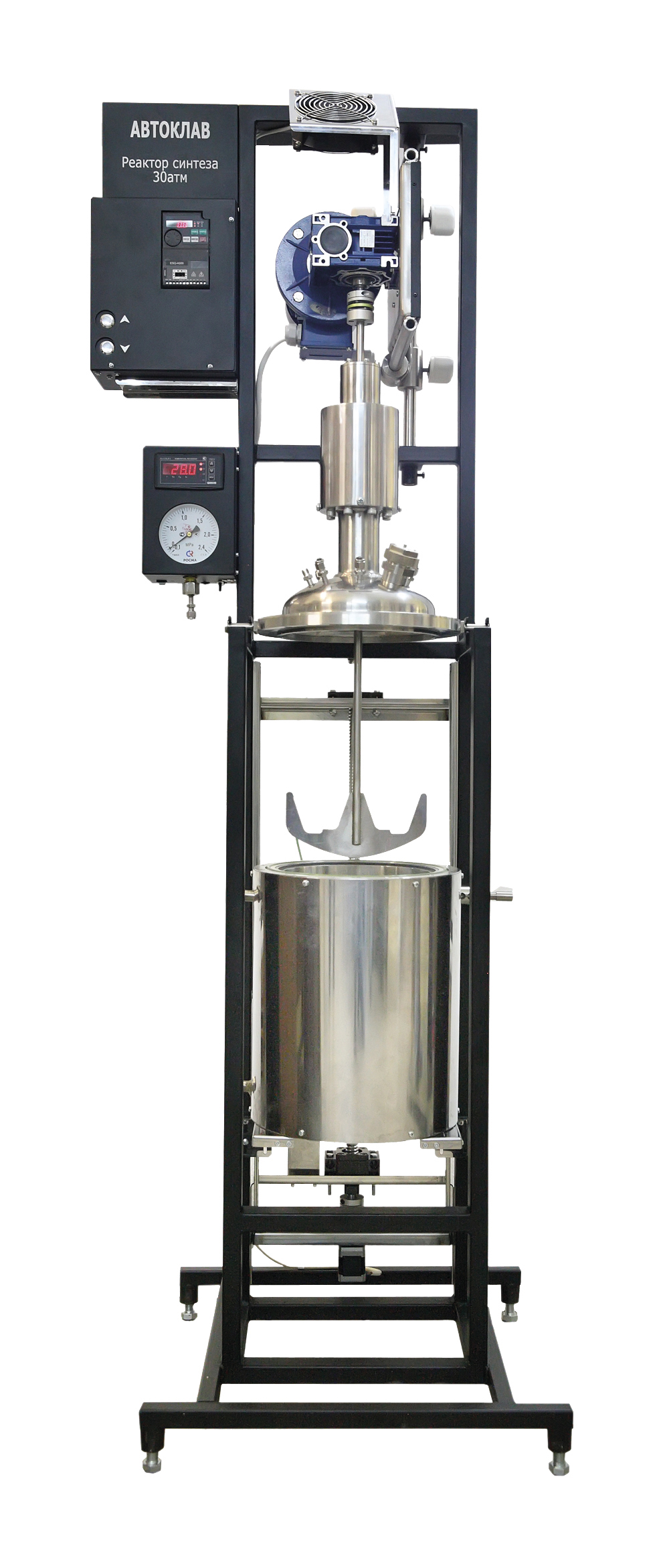
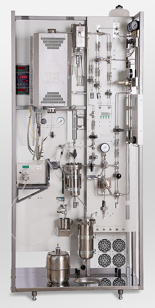
Currently, a facility is being developed to study and improve the processes of thermal cracking of super viscous oil (SVN) and heavy oil products (Fig. 7). The process of thermal cracking takes place with the participation of hydrogen donors. Donor-solvent cracking is a potentially promising non-catalytic process for the upgrading of SVN, in which the main task is to reduce the viscosity for pipeline transportation. At the same time, the main advantages are minimization of irretrievable losses (coke and gas) and the possibility of varying the composition of the product (distribution of light and medium distillate fractions) by selecting the parameters of the technological regime and the composition of hydrogen donors.
The decrease in reserves and production volumes of low – viscosity, so-called "light" oils in many oil-producing countries, including Russia, necessitates the involvement in the economic turnover of unconventional, relatively new for oil refining sources of hydrocarbons, primarily heavy oils and natural bitumen. The problem of heavy oil refining is not new, but still remains relevant. To date, Russian refineries do not have acceptable technologies for processing heavy oils, and therefore they are pre-mixed with light oil or light distillates. Processing of high-viscosity oils is very difficult, energy-intensive and, as a result, in many cases it is low-profitable and even unprofitable.
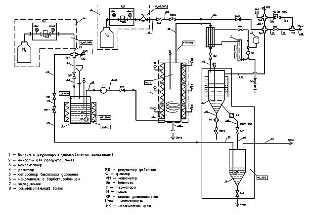
Fig. 7: The pneumatic circuit setup for studying the processes of thermal cracking.
Currently, the most common are thermocatalytic processes of advanced oil refining, but they do not provide enough effective technical and economic indicators in the processing of heavy raw materials. One of the problems of their processing is associated with a high content of high-molecular compounds - resins and asphaltenes polynaphthalene molecules in which is concentrated a large portion of the heteroatoms. These compounds have a high molecular weight, are prone to condensation and formation of coke during processing, deactivate catalysts. In this regard, the creation of methods of deep destruction of resinous-asphaltene components of heavy oils and natural bitumen, obtaining from heavy crude oil lighter oil, is one of the most important tasks of the oil refining industry.
To this day, various companies of the USA and Canada have developed several variants of such processes. Their essence lies in the fact that the heavy oil residue is mixed with a disssolvent (solvent) - a hydrogen donor, which is often used oil fractions of naphthenic hydrocarbons, less often - pure naphthenes (for example, decalin, tetralin, etc.). The design of donor-solvent thermal cracking can be illustrated using the example of the company «Gulf Canada» process: heavy oil feedstock is mixed with a hydrogen donor at a pressure of 35–56 atm and fed into a tube furnace, where it is heated to a temperature of 410–460 °С. Next, the mixture is placed in a remote reactor (soaking section), where it is kept for a certain time.
The products of donor-solvent cracking are then subjected to fractionation in a separator and in atmospheric column into gas, naphtha and middle distillates. The latter, after hydrogenation in a special unit according to the usual technology in the presence of standard catalysts, are recycled as a hydrogen donor. The remaining contents of the atmospheric column are sent to vacuum distillation to produce vacuum gas oil and residue. As a result, it is possible to convert about 60% of heavy oil raw materials (fuel oil, tar) to distillates.
Experts of the Institute of Organic and Physical Chemistry named after A.E. Arbuzov of the Kazan Scientific Center of the Russian Academy of Sciences conducted in the high-pressure reactor (autoclave) experiments on heat treatment of the UVO of the Ashalchinskoye field (PJSC "Tatneft"). To reduce the viscosity of oil, various hydrogen donors (tetralin and oil fractions) were used at a pressure of 3–21 MPa and a temperature of 375–470 °C. The amount of hydrogen donor in the reaction mixture was 5 or 10%. It was revealed that during thermolysis with a hydrogen donor with a mass content of 5–10% at a temperature of 410–420 °C and a pressure of up to 3 MPa, oil with a viscosity of 100 mm2/s (reduction by 30 times) can be obtained, in which the coke content is not fixed.